Glossary (Preparation)
Alarms
RKC Alarm Implementation Overview
Based on the RKC controller model, the core alarm functionality is defined as either an “Alarm” or as a “Digital Output”. Digital Outputs are used in conjunction with Events to generate the desired alarm. For models with Alarms, the number and type of Alarms is specified in the model code. For models with Digital Outputs, the number of Digital Outputs is specified in the model code. The Events (alarm types) are then assigned to the Digital Outputs in the Quick Start Code. If no Quick Start Code is identified, the end user will need to configure the Events for each Digital Output. Alarm types originally specified in the model code can also be changed by the end user.
Basic Alarm type definitions
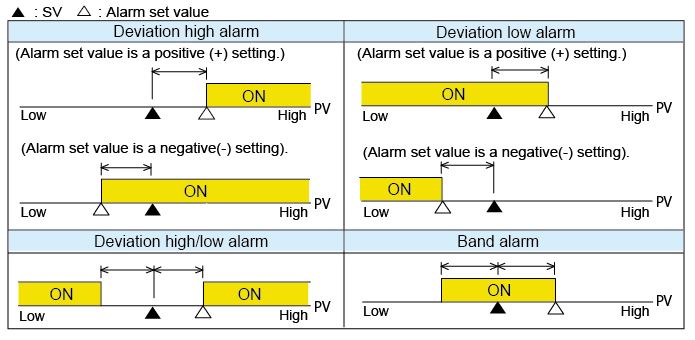
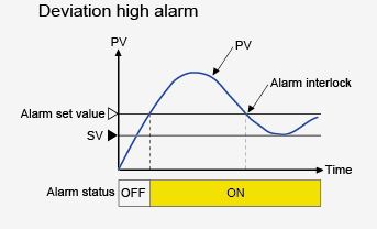
Deviation Alarm – This alarm is activated if the deviation [Measured Value (PV) – Set Value (SV)] reaches the alarm set value. Therefore, the Deviation Alarm is relative to the Set Value and changes as the Set Value changes. It is important to note the difference between entering an alarm set value greater than zero and less than zero.
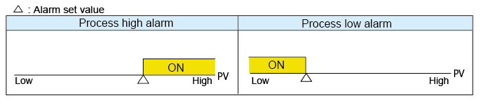
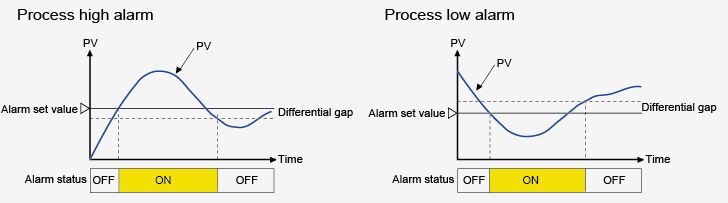
Process Alarm – An alarm is generated if the Measured Value (PV) reaches the alarm set value. This alarm set value is an absolute setting and is not impacted by the Set Value (SV).
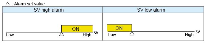
Set Value Alarm – An alarm is generated when the Measured Value (PV) reaches the set value.
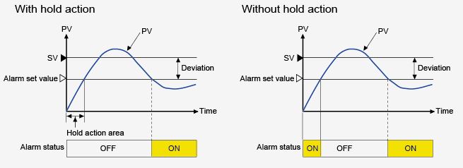
Hold Action
When Hold Action is ON, the alarm action is suppressed at Power-up, and during a STOP to RUN transition. The alarm will be suppressed until the measured value has entered the non-Event (Alarm) range.
Re-Hold Action
Re-Hold Action prevents unwanted alarm activation when the controller Set Value is changed. The Re-Hold action suppresses the alarm at Power-up, STOP to RUN transition, and after a Set Value change. For Set Value changes, the alarm will be suppressed until the Measure Value (PV) has entered the new non-alarm range. When Re-Hold is Off, the alarm output will be activated when the Set Value is changed. Re-Hold action is only available for deviation high, deviation low, and deviation high/low.
Differential Gap
Prevents chattering of the alarm relay due to the Measured Value fluctuating around the Alarm set value. The Event (Alarm) “On” set value is different from the Event (Alarm) “Off” set value based on the Differential Gap value.
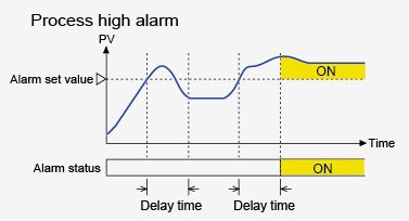
Event (Alarm) Delay Timer
When an Event (Alarm) condition becomes active, the output is suppressed until the Event Timer set time elapses. If the Event output is still active after the delay time has expired, the Event (Alarm) output will become active.
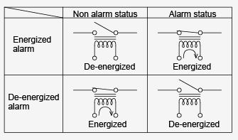
Energized and De-Energized Alarm Relays
Determines the “ON” and “OFF” states of the Event (Alarm) Relays.
Alarm or Event Interlock
When Alarm Interlock is implemented, the Event or Alarm relay will latch when an alarm condition occurs. It must be reset to the non-alarm state by using front panel keys, digital inputs, or communication commands.
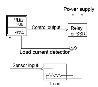
Heater Break Alarm
The HBA function detects a fault in the heating circuit by using a Current Transformer (CT) to monitor the current flowing through the load and then comparing it to the HBA set value. Two Heater Break Alarms are available on some controllers, which allows monitoring of three phase circuits. The Heater Break alarm is activated in the two cases described below.
Load current can be displayed on the controller front panel
Low or No Heater current flow
When the control output is “ON” and the current transformer input value is equal to or less than the Heater Break Alarm set value for the preset number of consecutive sampling cycle, an alarm is activated.
Over current or short-circuit (Heater Current cannot be turned off)
When the control output is “OFF” and the current transformer input value is equal to or greater than the Heater Break Alarm set value for the preset number of consecutive sampling cycle, an alarm is activated.
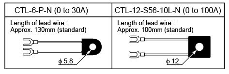
RKC supplies a 0-30amp and 0-100amp Current Transformer (CT) options for monitoring load current.
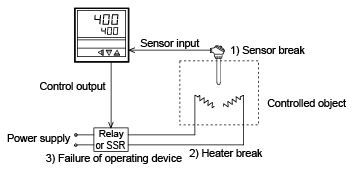
Control Loop Break Alarm
The Loop Break Alarm (LBA) is used to detect a control loop failure due to a failure of the load (heater), external actuator (SSR, magnetic relay, etc.), or input sensor (thermocouple, RTD). The Loop Break Alarm is set as a function of time and the LBA timer is activated when the controller output reaches 0 % (Off) or 100 % (Full On). The Loop Break Alarm monitors variation of the Measured value (PV) for the length of the LBA timer cycle. If the Controller output is 100% (Full On) and the Measured Value does not rise by at least 2° C (F) during the LBA timer cycle, the Loop Break Alarm will be activated. Similarly, the Loop Break Alarm will be activated if the heater output is 0% (Off), and the Measured Value does not fall by at least 2° C (F) during the Loop Break Alarm cycle time. No external hardware is required for the Loop Break Alarm.